
www.industryemea.com
17
'21
Written on Modified on
Designing Motion Control and Precision Positioning Equipment for High Vacuum and Ultra-High Vacuum Applications
How motorized positioners meet requirements of vacuum applications through specific design, selected materials and components, and vacuum-enabling manufacturing and quality control processes.
This whitepaper focusses on motorized positioners for vacuum applications and describes how those are designed, manufactured and tested regarding their specific requirements. It also allows a closer look at the permissible materials for different vacuum levels and quality control measurements that can be performed.
Vacuum Applications
Vacuum applications are becoming increasingly important because of new technologies that can only be used in a vacuum. Lenses are coated in the optics industry and fiber and laser optics, as well, as sensitive detectors are manufactured in a vacuum. In the production of microelectronic circuits, vacuum conditions ensure safe handling of sensitive components. Both the aerospace industry and the automotive industry use electron beam processes to minimize angular distortion and transverse shrinkage during welding of microcomponents or thick-shelled workpieces. The surface and material analysis with the help of scanning electron microscopy (SEM), transmission electron microscopy (TEM) or X-ray tomography must be done in a vacuum. Nanocharacterization and nanostructuring is also dependent on a vacuum environment due to the methods used, such as ion-beam focusing.
Ultra-high vacuum and very clean conditions are required for EUV lithography that is intended to allow further reduction of feature sizes in the semiconductor industry, and also the development of Qubits for advancing quantum computing would be unthinkable without vacuum technology.
Both scientific research and industry require different vacuum classes for all of these and many other applications, and the appropriate equipment must be provided.
There are clearly defined challenges for operating positioning systems. One of them is typically limited installation space. It is also important to avoid contaminating the vacuum chamber with particles by abrasion or outgassing, as well as excessive heat input.
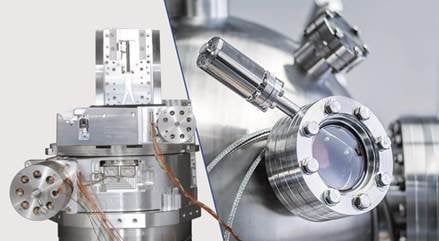
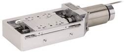
Manufacturers of motion control and precision positioning equipment that are experienced in vacuum technology and applications, such as PI, can offer standard and customer-specific drive technologies that are precisely tailored to the requirements of the vacuum application (as shown in Figure 1).
This includes motorized positioners with specially designed DC or stepper motors that allow large travel ranges. Furthermore piezo actuators, piezo systems and piezo motors, as well as parallel kinematic hexapods, are also available in different designs with respect to force, dynamics and travel ranges.
Challenges in Vacuum
It is important to analyze the demands of a specific application in order to select the required vacuum class. Additionally, to the final pressure, the outgassing rate is relevant because it determines the partial pressure of specific residual components. For example HCs (hydrocarbons) may be introduced into the vacuum chambers unintentionally due to the use of grease or plastic components not compatible for use in a vacuum. HCs are fragmented by strong UV light or X-rays, and therefore, they are especially critical in laser applications in the UV range and in beamline applications. HC fragments deposited on optics surfaces pollute or can even damage the in-vacuum optics or the test sample.
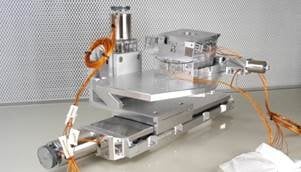
Four-axis system for an ultra-high vacuum application. (PI)
Vacuum Classes
Vacuum is defined as pressure lower than normal atmospheric air pressure {DIN 28400}, and is measured in either [hPa], [mbar] or [Torr]. Different levels of vacuum classes are defined: fine, high, ultra-high and extreme. While high and ultra-high are commonly applied, extremely high vacuum is rarely necessary. To determine the required vacuum class, it is necessary to know the application as well as possible (as shown in Table1).
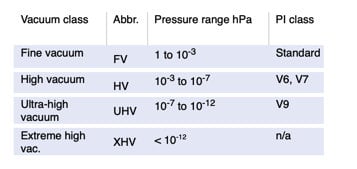
Table 1 – Definition of vacuum classes based on pressure ranges. (PI)
Outgassing Rate
The outgassing rate is the next relevant specification because it represents the partial pressure of specific residual components. Outgassing is the detachment of volatile molecules that are absorbed or adsorbed on the surface, or in the volume of a material.
Because the rate of outgassing defines the pressure in the system (together with the capacity of the vacuum pump), outgassing prohibits fast achievement of low pressure values. In addition, the outgassing compounds deposit on surfaces of optical elements or other sensitive devices and can obscure or damage them.
Overall, motorized positioners are required with low outgassing. Furthermore, the residual gas must contain very little or no HCs, and no metals with high vapor pressure such as zinc, lead, or cadmium.
Vacuum-Compatible Equipment
Because outgassing is a challenge for creating and maintaining clean high-vacuum environments, the right choice of materials and treatments is compulsory in the design and production of vacuum systems.
To achieve a high vacuum (HV) or an ultra-high (UHV) vacuum-compatible motorized positioner, three main issues have to be considered: material selection, design, as well as manufacturing and commissioning processes.
Manufacturers, such as PI, offer specific vacuum-ready catalogue items for selected product series that are already compatible for high vacuum (HV) or ultra-high vacuum (UHV), or can be modified on request for use in a vacuum. PI products, for example, achieve atmospheric pressure up to 10-9 hPa. In some cases, 10-10 hPa can be reached.
Vacuum-Ready Motorized Positioners
Using PI as an example, there are three specific standard vacuum classes which the company makes available: V6 for high vacuum specifications; V7 for higher cleanliness/pressure demands; and V9 for ultra-high vacuum requirements. Table
2 exhibits the different measures taken to achieve the corresponding vacuum class.
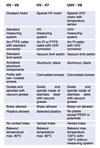
Different measures to achieve corresponding vacuum classes. (PI)
Example of a vacuum-ready linear stage (L-509). (PI)
Materials in Vacuum-Ready Products
Common electrical and electronic equipment contains components that either do not suit vacuum applications or only limitedly. These comprise cables, motors, scaling systems, connectors, limit switches and others. Common cables are usually shielded with PVC insulation. Common motors are lubricated with grease or oil, with high vapor pressure containing HCs. And common electronic parts are embedded in plastics with high outgassing rates.
Specific product features should be implemented on all these to avoid outgassing from these components that in total contribute to a clean vacuum environment.
Replacing PVC cables with PTFE or polyimide-shielded braids is technically simple but expensive. Polyimide in particular, has the necessary cleanliness for use in a vacuum, but it absorbs considerable water molecules, which increases the pump-down period drastically. Therefore, only the number of braids necessary should be used for operating the positioning system. The braids should be as short as possible and ideally, the vacuum chamber is also designed for short cables.
Motors modified for vacuum (as shown in Figure 3) have several holes for venting, and are equipped with polyimide-shielded motor coils that ideally have a temperature sensor installed in the motor. Temperature control is important for two reasons: Firstly, the motor should be operated at a point below excessive heat generation, which means that slow driving is recommended. Secondly, a temperature-controlled bakeout process must be performed by applying current to the motor, at least for UHV systems.
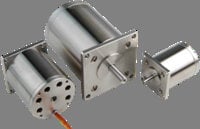
Typical motors for UHV applications: outgassing holes, polyimide-shielded braids, and clean stainless steel surface. (PI)
Therefore, all components for UHV stages must be able to sustain heat-up to a certain temperature. Typically, PI for example, sets this temperature to 120°C for stages with a scaling system, and to 150°C for stages without. Due to the huge number of windings of the motor coils, the amount of polyimide is very high, and therefore, a large amount of adsorbed water must be baked out. Specially designed two-phase stepper motors are implemented in the UHV products as shown in the image above.
Common connectors and limit switches cannot be used in vacuum beyond 10-6 hPa due to their high-outgassing plastic components. They are supplemented by components made of low-outgassing plastics (for HV) or ceramics, PEEK and metal (for UHV), as shown in Figure 4. The pins of the connectors and the contacts of the switches are not soldered, but clamped, crimped or laser welded.
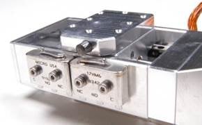
Example of small linear vacuum stage with UHV limit switches. (PI)
The selection of materials for the chassis of the positioner is limited. For example, copper-zinc alloys should not be used in vacuum systems. Such materials are replaced by bronze, if possible. Other standard plastic parts are substituted by PEEK, ceramics or metal components for UHV products.
Design-for-Vacuum
Substitution of standard materials with vacuum-compatible materials, as described above, is a strict requirement of vacuum stage design. Another requirement is the reduction and minimization of the surface of the positioner. The surface of the uncoated body is not sand-blasted for vacuum stages. Covers for protection against contamination are usually not required for vacuum stages. Protective shields for limit switch electronics are not necessary in the case of mechanical limit switches.
The third and very important requirement in vacuum stage design is the prevention of virtual leaks. A virtual leak is a trapped volume connected to the vacuum side of a chamber. The gas in this trapped volume cannot be pumped out easily due to only narrow paths connecting to the vacuum chamber. This results in slow outgassing and appears to be a leak in the vacuum system. Poor design is the major cause of virtual leaks, not only for positioning stages, but for vacuum chambers and vacuum equipment in general.
Trapped volumes are usually caused by unvented or poorly vented blind tapped holes. These are either at the tip of a screw or under the rim of the screw head. Furthermore, holes that are covered, either when mounting the positioner on a base plate or fixing a sample on the positioner, often cause virtual leaks.
In the case of virtual leaks caused by screws, the use of vented screws is recommended. Vented screws have a hole down the length of the screw to avoid trapped volumes, as shown in Figure 5. In this way, the trapped volume can be vented. Furthermore, the head of the screw has a groove to ensure venting of the cavity under the screw head. If the hole is covered by the positioning unit, which then causes a virtual leak, it must have either a perforation or an air vent groove.
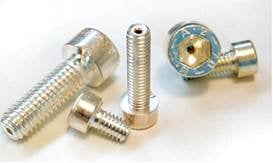
Example for Design-for-Vacuum: Drilled silver-plated screws for venting of trapped volumes in vacuum. (PI)
Vacuum-Enabling Manufacturing and Commissioning Processes
Before a vacuum positioner is assembled, all pure metal parts undergo a cleaning process in an ultrasonic bath. Electrical and electronic units are wipe-cleaned. Standard lubricated components such as bearings and guides are degreased, cleaned and lubricated with special vacuum grease. Ultrasonic-cleaned components are dried in a climate chamber.
Assembling of a stage is carried out in a cleanroom or in a laminar flow system. After assembling, the stage must pass a performance test in a clean environment. Vacuum tests are performed for each type of stage, and when vacuum-critical changes are made to the product.
After assembling, the system is packed in vacuum-sealed bags, protected against dirt, air, and humidity: First, the stage undergoes a baking process in a climate chamber. After packing and sealing in an inner vacuum bag, the stage is then put into a second, outer vacuum bag which is then vacuum sealed completely.
Accessories for Vacuum-Ready Products
Accessories used within the vacuum environment can also be provided in vacuum versions, such as suitable feedthroughs and cable adaptors. Further accessories such as flanges or connectors are available for vacuum-ready products. However, for electronic devices like controllers and amplifiers it is recommended to use them outside the vacuum environment.
Test and Quality Control
Vacuum-ready products undergo standard testing. Following are examples of how these products are tested by PI. Additionally, customized tests can be ordered for individual vacuum applications. PI has several vacuum chambers with different volumes for bakeout and mass spectrometry.
For testing single components or for testing small stages, a chamber is available with a volume of approximately 10 l. The small vacuum chamber is equipped with a pump stand consisting of a 400 l/s (N2) turbomolecular pump and a pressure sensor for continuous pressure sensing, which means that pressures below 10-10 hPa can be reached. A heating facility allows bakeout temperatures up to 200 °C.
A large chamber (see Figure 6) with a volume of 260 l is designed for large stages up to a length of 800 mm, hexapods, and for multi-axis systems. A pump stand with a 700 l/s (N2) turbomolecular pump and a pressure sensor allow testing down to 10-9 hPa. Bakeout temperatures up to 150 °C are possible with the integrated heating system
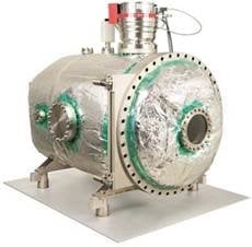
Large vacuum chamber test facility at PI. (PI)
For in-vacuum operation tests on stages and flanges of different sizes are available for motor current, linear encoder, limit switches, temperature sensors etc. with various feedthroughs. If interferometric measurements are required, or visual observation of processes is necessary, both chambers can be equipped with inspection windows. A quadrupole mass spectrometer is available for real-time RGA (residual gas analysis) between 1 amu to 200 amu, which can be attached to both chambers.
PI classifies and verifies the vacuum products by vacuum pressure measurements and RGA (residual gas analysis) in the vacuum chambers. Depending on which vacuum level needs to be reached, the chambers and stages are baked out accordingly.
Parallel to pressure measurements, RGA scans are performed at important points during the vacuum test. Residual ionized molecules in the chamber are separated in the mass filter of the spectrometer. A downstream Faraday cup with secondary electron multiplier allows measuring with low pressure detection limits. Outgassing of water, HCs or other impurities can be determined, but the desorption processes can also be traced and (virtual) leaks can be detected.
Standard High Vacuum Test
As an example for a relatively large contamination potential, a high-vacuum version of the L-509 linear axis is tested inside a vacuum chamber. The results are shown in Figure 7 and 8. A pump-down pressure curve for the stage is recorded using the small chamber (10 l, 400 l/s pump). After pumping down for two days, a final pressure in the order of 10-7 hPa is reached.
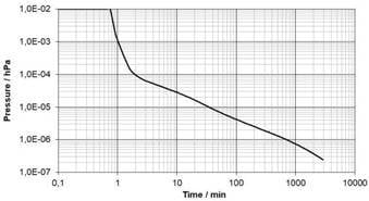
Exemplary pump-down pressure curve of vacuum-ready linear stage L-509 in HV.
After pumping for two days, a final pressure in the order of 10-7 hPa is reached. (PI)
A RGA was made after 48 hours pumping time and shows a spectrum that is dominated by the water peaks (16 amu to 18 amu), followed by the nitrogen signal (28 amu). All other contributions are in an order of less than 1% of the water peak. Nevertheless, HC contributions are observed over the full range of measured masses and sum up to a considerable HC partial pressure.
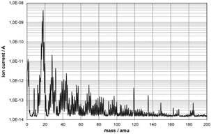
Exemplary RGA scan of vacuum-ready linear stage L-509 in HV.
In addition to the strong water peak at 18 amu, a considerable contribution of HCs is observed. (PI)
Standard Ultra-high Vacuum Test
For ultra-high vacuum stages, the pump-down period in the vacuum chamber is followed by a bakeout process of several hours or days, depending on the size of the stage. The stage is kept in thermal contact with the vacuum chamber, which is heated. The permitted bakeout temperature is between 80°C and 150°C, determined by the components the stage is assembled from. Additionally, because all vacuum motors outgas during operation and motor warm-up, the motor of the stage is heated by applying current to the motor coil in order to outgas most of the residual volatile compounds. The motor temperature should be about 40 K to 50 K above the overall bakeout temperature, and is controlled via an integrated temperature sensor. Furthermore, the motor should be moved slowly during the whole bakeout process. In this way, homogeneous heating of the motor and therefore continuous bakeout of the volatile compounds is ensured. As an example for an UHV product, vacuum test results from a linear stage are shown in Figure 9. This measurement is made in the same chamber as previously mentioned (10 l, pump 400 l/s). After a pump-down sequence of 15 hours, the stage was heated to 150°C for 8 hours.
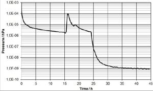
Exemplary pump-down pressure curve of a vacuum-ready linear stage (UHV). (PI)
When switching the heater on, the pressure in the vacuum chamber increases by almost two orders of magnitude, and slowly decreases during the heat-out period. After switching the heater off, the effect of bakeout can be observed: the pressure in the vacuum chamber decreases by more than three orders of magnitude, reaching pressures below 10-9 hPa at roomtemperature.
After the cool-down period, a RGA spectrum was made. In the spectrum shown in Figure 10, hydrogen (1 amu to 2 amu) dominates, which is hard for a turbo pump to remove. All other signals are at least 10 times smaller. Hydrogen is the exception and water is still the largest part of the residual gas. However, it exceeds other contributions by a factor of two instead of fifty as in the example for HV. HCs are strongly reduced but above 91 amu and there are practically no significant values in the spectrum.
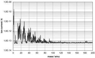
RGA scan of a vacuum-ready linear stage in UHV. Contributions of HCs above 91 amu can be neglected.
The water peak at 18 amu is comparable to other contributions. (PI)
Initial Startup and Operation
Before unpacking the product, the outer bag must be wiped clean and removed before the product is moved into the clean area. Then, cleanroom gloves have to be worn when opening the inner bag in the clean area where the product should be kept.
Before the desired vacuum level is reached, conditioning of the stage in a vacuum environment must be performed depending on the vacuum class of the stage.
In the case of HV stages, it is usually sufficient to pump for several hours or days to reach the HV vacuum level, depending on the size of the stage and the pumping capacity of the vacuum pump. Motor bakeout, by running the motor, supports the outgassing process. HV stages are designed for temperatures up to a maximum of 80°C.
For ultra-high vacuum stages, the pump-down period should be accompanied by heating the stage and the vacuum chamber, as well as additional bakeout of the motor by current feed. For temperature control of the motor, the UHV motors are equipped with a temperature sensor. During heating, the temperature of the motor should be 40 K to 50 K above the stage temperature. The heat-out process of several hours or days also depends on the size of the vacuum stage and the capacity of the pump. A good thermal contact to the heated vacuum chamber is essential for a fine bakeout result. After the vacuum-chamber has cooled-down, the desired vacuum level is reached.
Customized Vacuum-Compatible Products
Because many parameters for vacuum applications must be taken into account before selecting, a thorough review of technical requirements will be performed to determine the best fitting solution.
Grease and/or oil lubrication is present in all vacuum stages with the exception of oil-free UHV-conditioned stages. Oil-free UHV vacuum conditioning is available for a selection of stage models. Most stages can be equipped with optional linear encoders (angular encoders for rotary stages). Initially, a standard vacuum positioning system is selected to meet the application requirements. If this selection is not satisfying, alternative customized products can be custom-designed.
www.pi-usa.us
