
www.industryemea.com
16
'26
Written on Modified on
GEMÜ Simplifies Semiconductor System Integration with Extended Valve Pressure Ranges
The pneumatically operated GEMÜ C60 diaphragm valve now features tailored control pressure ranges and an optimized cap locking mechanism for high-purity semiconductor factory applications.
www.gemu-group.com
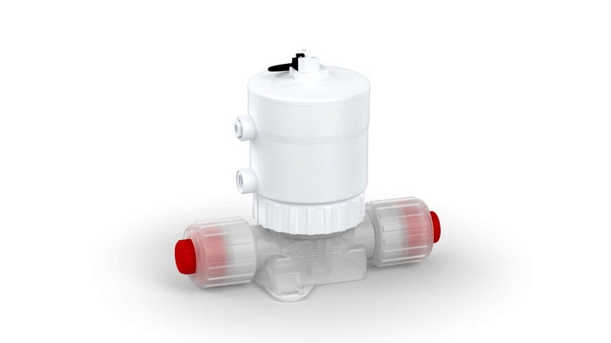
Integrating pneumatically actuated valves into ultra-high-purity fluid distribution networks presents persistent pneumatic supply engineering challenges, particularly within modern semiconductor fabrication facilities. When plant pneumatic networks operate with varying baseline air pressures across sub-fab utility levels and cleanroom point-of-use distribution manifolds, narrow valve control pressure windows often force engineers to install additional local pressure regulators or resize pneumatic supply lines. To address this system design constraint, GEMÜ has updated the GEMÜ C60 pneumatically operated 2/2-way diaphragm valve with extended control pressure ranges, enabling engineers to align valve actuation directly with existing plant pneumatic supply architectures.
Engineering Role of Diaphragm Valves in Semiconductor Fluid Systems
In semiconductor manufacturing, chemical delivery systems, ultrapure water (UPW) loops, and slurry distribution networks require strict isolation between the process medium and the actuator mechanism to prevent particulate shedding and metallic contamination. Pneumatically operated 2/2-way diaphragm valves serve as primary shutoff and control elements at the supply and distribution levels of semiconductor fabs.
In a 2/2-way diaphragm valve architecture, a flexible elastomer or fluoropolymer diaphragm isolates the wetted fluid path from the pneumatic actuator assembly. Compressed air enters the actuator chamber to displace a piston or diaphragm actuator element against a spring pack (in fail-safe configurations) or against opposing pneumatic pressure, lifting or pressing the valve diaphragm onto a weir or seat. Because different actuator sizes generate varying mechanical forces relative to process line pressure, the required pilot air pressure — known as the control pressure — must be carefully matched to both the actuator geometry and the fail-safe control function.
Extended Control Pressure Specifications and Mechanical Updates
By expanding the permissible control pressure envelopes across multiple actuator sizes, the updated GEMÜ C60 reduces the need for auxiliary pressure conditioning hardware in multi-valve manifolds and gas or chemical distribution boxes. According to technical specifications released by GEMÜ on November 9, 2026, the revised control pressure parameters are differentiated by control function and actuator size:
For the Normally Closed (NC) control function, where spring force holds the valve shut in the absence of pilot air, the allowable control pressure spans 4 to 7 bar, 4.5 to 7 bar, or 5 to 7 bar, depending on the specific actuator size selected for the application.
For the Normally Open (NO) control function, where spring force holds the valve open until pilot air is applied to close the flow path, the maximum permissible control pressure is specified at 5 bar for actuator sizes 1 through 3, and 4.5 bar for actuator size 4.
Alongside the pneumatic envelope expansion, GEMÜ modified the mechanical retention of the transparent indicator cap mounted on top of the actuator housing. The locking device on the transparent cap has been optimized to provide a more secure mechanical fit within the actuator housing, protecting visual optical position indication and preventing inadvertent loosening during installation, maintenance, or vibration exposure in dense valve clusters.
Integration into Semiconductor Supply and Distribution Workflows
Within semiconductor fabrication plants, the GEMÜ C60 operates primarily at the bulk supply and sub-fab distribution tiers, managing high-purity media before fluids reach individual wafer processing tools. In these environments, dozens of valves are frequently grouped into compact valve manifold boxes (VMBs) or chemical distribution modules where space is constrained and pneumatic tubing runs are standardized.
Allowing NC configurations to operate across ranges starting at 4 bar, 4.5 bar, or 5 bar up to 7 bar provides greater tolerance for pressure drops across long pneumatic tubing runs or multi-valve pilot manifolds. Simultaneously, defining explicit upper control pressure limits of 4.5 bar and 5 bar for NO actuator configurations protects internal actuator components and diaphragm assemblies from over-pressurization without requiring complex custom pneumatic zoning.
Additional Context
This section details technical specifications and competitive benchmarking not included in the original product announcement.
In semiconductor fluid handling, pneumatically operated high-purity diaphragm valves are governed by stringent cleanliness and materials standards established by Semiconductor Equipment and Materials International (SEMI), such as SEMI F57 for polymer materials and components used in ultrapure water and liquid chemical distribution systems, as well as SEMI F19 and SEMI F20 for surface finish and metallic component purity.
Within this product category, compact 2/2-way pneumatically actuated fluoropolymer diaphragm valves are standard across cleanroom and sub-fab distribution systems. Comparable industrial valve series designed for high-purity semiconductor chemical and UPW distribution — such as the SMC LVP and LVQ series of high-purity air-operated chemical valves, the CKD AMD and GAMD series of cleanroom diaphragm valves, and the Parker Hannifin Veriflo and Partek high-purity pneumatic diaphragm valve lines — typically operate within nominal pilot air pressure ranges of 4 to 7 bar (approximately 58 to 101 psi) depending on valve orifice size, body material (commonly PFA or PTFE), and spring-return configuration.
Across these benchmark high-purity valve platforms, actuator sizing directly dictates the relationship between maximum working fluid pressure and minimum required pilot air pressure. Larger orifice valves require higher spring forces to seal against line backpressure in Normally Closed designs, raising the minimum threshold pilot pressure from 4 bar toward 5 bar, while Normally Open configurations commonly enforce lower maximum pilot pressure ceilings to avoid excessive closing force on fluoropolymer diaphragms and seats. The updated GEMÜ C60 pressure ratings align directly with these established semiconductor facility pneumatic supply standards, where clean dry air (CDA) or nitrogen pilot lines are typically regulated between 4.5 bar and 6.5 bar.
Edited by Evgeny Churilov, Induportals Media - Adapted by AI.
www.gemu-group.com
