
www.industryemea.com
17
'26
Written on Modified on
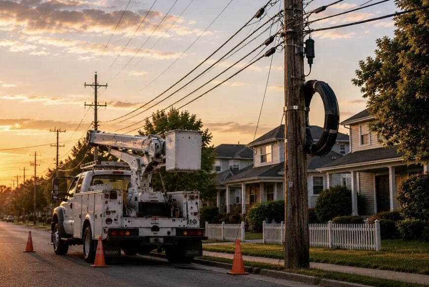
Belden launches PPC DiamonDrop fiber cable
Designed for last-mile/drop applications, it helps streamline on-site work while maintaining performance expectations for single-fiber connectivity in outside plant environments.
www.belden.com
Belden has announced the launch of its PPC DiamonDrop™, a single-fiber drop cable engineered for last-mile and drop broadband applications. Developed for outdoor aerial and underground infrastructure installations, the cable simplifies field preparation and enhances termination efficiency.
Last-Mile Deployment and Mechanical Optimization
As regional broadband expansion accelerates—particularly across rural and unserved geographic areas—installation teams face significant requirements to connect subscribers rapidly while maintaining deployment consistency and minimizing rework. DiamonDrop addresses these operational pressures by streamlining on-site cable preparation without necessitating modifications to established deployment standards or company operational procedures. Compared to traditional lightweight flat drop cables, the product offers enhanced handling usability while maintaining compatibility with industry-standard connector options and common outside plant field practices.
Structural Performance and Environmental Durability
The single-fiber cable incorporates a proprietary core layout designed to deliver specialized handling characteristics during cable splicing and field preparation:
- Jacket Separation: The unique core design enables the outer jacket to peel away cleanly from the internal structures when exposing the 900 µm buffered fiber, removing the requirement for specialized stripping tools and minimizing the risk of accidental fiber damage.
- Hardware Interfacing: The mechanical design ensures compatibility with a broad array of industry-standard connectors and optical hardware components, supporting standard field termination approaches.
- Outside Plant Reliability: The assembly is encased in a weather- and UV-resistant protective jacket engineered to withstand long-term environmental degradation in outside plant conditions.
- Mechanical Spans: The cable is constructed for both aerial and underground deployments, including underground conduit routing or direct burial practices. Architecturally, it supports overhead spans up to 150 feet when subjected to National Electrical Safety Code (NESC) heavy load conditions.
- Regulatory Compliance: The product series is fully RoHS 2011/65/EU compliant, with dedicated Build America, Buy America (BABA) compliant production options available for infrastructure project selection.
According to Doug Jones, VP of Product and Innovation for Belden Broadband Solutions, the cable platform was designed specifically to eliminate cable preparation and termination difficulties, which represent one of the most common complications in last-mile fiber work. Jones noted that the core architecture allows deployment crews to execute field installations with greater quality confidence and consistency across both aerial and underground environments. The drop cable is positioned for FTTX outdoor aerial and underground deployments serving telecommunications providers, rural broadband initiatives, and data infrastructure projects.
Additional Context
This section details technical specifications not included in the original news release.
Fiber-to-the-Home (FTTH) drop cables represent the final segment of the optical distribution network, bridging the connection between the localized distribution splice closure and the subscriber premises. Standard flat drop cables typically feature a rigid, tightly bound outer polyethylene jacket reinforced by parallel dielectric or metallic strength members, such as Fiberglass Reinforced Plastic (FRP) rods. Conventional preparation requires technicians to use specialized shaving or splitting tools to slice through the high-density jacket along the strength members to access the central buffer tube. This manual procedure introduces a high risk of tool slippage, which can score or micro-bend the optical fiber, inducing high localized attenuation or outright mechanical failure under structural tension.
Clean-peeling jacket geometries eliminate this risk through co-extrusion manufacturing techniques that introduce weak shear planes or a distinct material separation layer between the outer sheath and the inner 900 µm tight buffer layer. This structural formulation allows the technician to slit the tip and peel the jacket apart smoothly by hand using minimal separation force.
The 900 µm tight buffer layer provides secondary mechanical protection to the primary 250 µm acrylate-coated silica fiber, increasing the structural diameter to make the strand rugged enough for direct termination with mechanical field-installable connectors (such as SC/APC or LC/APC fast-connectors) without requiring a separate protective furcation tube.
Overhead deployment of drop cables exposes the optical line to continuous dynamic physical loads, including wind-induced galloping and ice accumulation. The National Electrical Safety Code (NESC) defines distinct geographic loading districts (Heavy, Medium, and Light) based on combined radial ice thickness, wind velocity pressures, and ambient temperatures. Under NESC Heavy loading guidelines, a cable span must withstand a simultaneous load of 0.5 inches of radial ice and a wind pressure of 4 pounds per square foot at 0°F (-18°C).
To sustain a 150-foot span under these severe environmental criteria without exceeding the maximum allowable fiber strain or causing signal degradation from macroscopic bending, the internal FRP strength members are engineered with a precise tensile modulus that limits sag and controls structural elongation, preventing mechanical stress from transferring directly to the internal glass core.
Edited by Romila DSilva, Induportals Editor, with AI assistance.
